Manual Vending Machine: A Comprehensive Guide
Dive into the world of self-made automated retail! This guide explores building vending machines using readily available materials‚
perfect for makers‚ hobbyists‚ and anyone desiring a unique‚ hands-on project․ Discover innovative designs and construction techniques․
Manual vending machines represent a fascinating intersection of ingenuity‚ resourcefulness‚ and the desire for convenient access to treats and small items․ Unlike their electrically powered counterparts‚ these machines rely on human interaction and simple mechanical principles for operation․ This approach opens doors to exciting DIY projects‚ allowing individuals to construct personalized vending solutions tailored to their specific needs and preferences․
The appeal lies in their accessibility; building a manual vending machine doesn’t require extensive technical expertise or expensive components․ Projects like those pioneered by makers such as Ryan Bates and Dejan Nedelkovski demonstrate the feasibility of creating functional vending systems using cardboard‚ wood‚ and basic mechanical parts․ These creations often blend functionality with playful designs‚ exemplified by gumball and pinball combinations‚ or even Oreo and milk dispensers․

This guide will delve into the core concepts‚ construction techniques‚ and potential customizations involved in building your own manual vending machine‚ offering a pathway to a rewarding and surprisingly practical DIY experience․
Historical Context of Vending Machines
The roots of vending machines stretch back to ancient Egypt‚ with automated holy water dispensers appearing as early as the 1st century AD․ However‚ the precursors to modern vending machines emerged in 17th-century England‚ featuring tobacco boxes with coin mechanisms․ These early devices‚ while rudimentary‚ established the core principle of automated dispensing․
The 19th century witnessed significant advancements‚ particularly with the invention of the first postcard vending machine in the 1880s․ This period saw a surge in vending machine innovation‚ driven by industrialization and a growing demand for convenient access to goods․ Early machines were entirely mechanical‚ relying on intricate clockwork mechanisms and levers – essentially‚ manual vending in its purest form․
The transition to electric vending machines began in the late 19th and early 20th centuries‚ but the fundamental principles of mechanical dispensing remained crucial․ Today’s DIY manual vending machine projects represent a return to these origins‚ celebrating the elegance and simplicity of purely mechanical automation․
The Appeal of DIY Manual Vending Machines
The resurgence of interest in DIY manual vending machines stems from a desire for tangible‚ hands-on projects in an increasingly digital world․ Building one offers a unique blend of engineering‚ creativity‚ and problem-solving‚ appealing to makers‚ Arduino enthusiasts‚ and hobbyists alike․ It’s a rewarding experience to construct a functional machine from basic materials․
Beyond the satisfaction of creation‚ these projects offer a cost-effective alternative to commercially available vending machines․ Utilizing readily available materials like cardboard and wood keeps expenses low‚ making it accessible to a wider audience․ The customization potential is also a major draw – builders can tailor the machine’s design and functionality to their specific needs and preferences․
Furthermore‚ manual vending machines provide an educational opportunity‚ demonstrating fundamental mechanical principles in a practical way․ They represent a playful intersection of nostalgia and innovation‚ offering a unique and engaging project for all ages․

Core Components & Materials
Essential building blocks include cardboard‚ wood‚ DC motors‚ nine-volt batteries‚ and hot glue․ Mechanical parts are crucial for dispensing‚ creating a functional system․
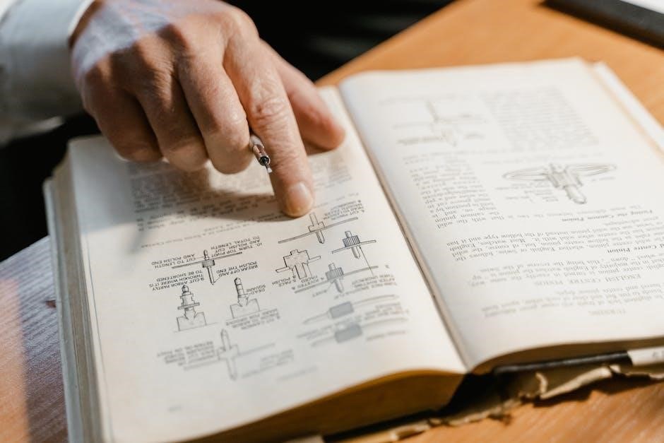
Essential Mechanical Parts
Constructing a manual vending machine hinges on carefully selected mechanical components․ Levers are fundamental‚ forming the core of dispensing mechanisms‚ allowing for controlled release of products․ Consider robust lever arms and precise pivot points for smooth operation․
Furthermore‚ rollers or rotating drums can facilitate product movement‚ especially in gravity-fed systems․ These need to be smoothly rotating and durable enough to withstand repeated use․
Chutes are vital for directing dispensed items to the collection area; their angle and smoothness are key to preventing jams․ Springs can provide assistance in returning levers to their starting positions or in gently nudging products forward․
Finally‚ consider using stoppers or barriers to regulate the flow of products and prevent multiple items from dispensing simultaneously․ Precise alignment and secure fastening of these parts are paramount for a reliable vending experience․
Sourcing Affordable Materials (Cardboard‚ Wood‚ etc․)
Building a manual vending machine doesn’t require expensive resources! Cardboard is an excellent starting point – readily available‚ free‚ and easily cut and shaped․ Repurposed boxes offer a sustainable and cost-effective base for your project․
For increased durability‚ consider incorporating wood – plywood scraps or reclaimed lumber are ideal․ These provide structural support for levers‚ chutes‚ and the overall frame․ Local hardware stores often sell offcuts at discounted prices․
Plastic containers‚ like bottles or tubs‚ can serve as product holders or dispensing channels․ Hot glue and tape are essential for assembly‚ keeping costs minimal․
Don’t overlook household items! Coat hangers can be bent into levers‚ and bottle caps can act as stoppers․ Resourcefulness is key to building a functional and affordable vending machine․
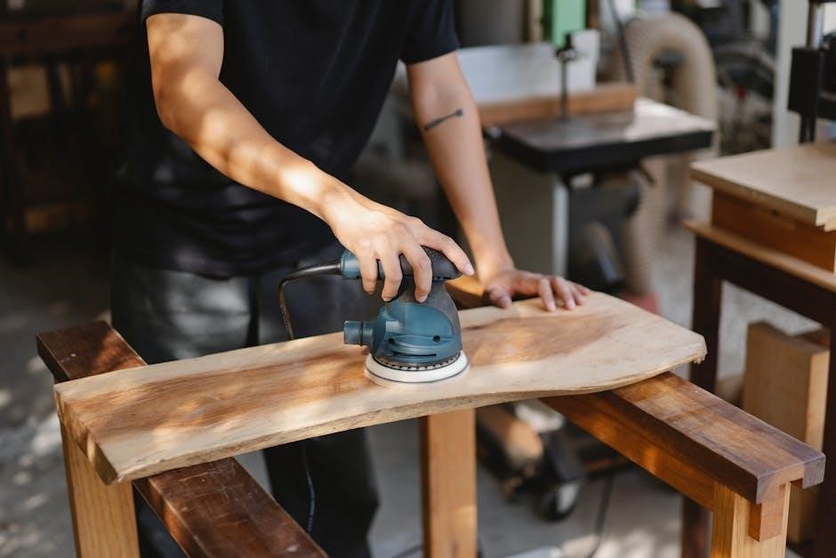
Tools Required for Construction
Constructing a manual vending machine demands a basic toolkit‚ but nothing overly specialized․ A sharp utility knife or box cutter is crucial for precisely cutting cardboard and other materials․ A sturdy pair of scissors will also prove invaluable for smaller adjustments and detail work․
A hot glue gun is essential for quick and secure bonding of components․ Ensure you have plenty of glue sticks! A ruler or measuring tape guarantees accurate dimensions and alignment․ A pencil is needed for marking cut lines and design elements․
Depending on the materials used‚ a handsaw or jigsaw might be necessary for cutting wood․ Safety glasses are paramount to protect your eyes from debris․ Consider a drill for creating holes for levers or dispensing mechanisms․
Basic pliers can assist with bending wire or manipulating small parts․ These tools will empower you to bring your vending machine vision to life!

Construction Techniques & Designs
Explore diverse building methods! From simple cardboard structures to more robust wooden frames‚ learn to craft functional vending machines with innovative dispensing systems․
Basic Cardboard Vending Machine Design
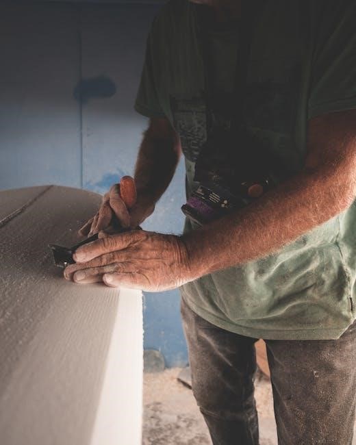
Embark on a beginner-friendly project! Utilizing cardboard as the primary material offers an accessible and cost-effective entry point into vending machine construction․ Begin by designing a box-like structure with a dispensing slot and a product loading area․ Reinforce corners and seams with ample tape to ensure structural integrity․
Consider a modular design‚ creating separate compartments for different products․ This simplifies restocking and prevents jamming․ The front panel should feature a clear window to showcase the available items․ Precision cutting is crucial for smooth operation; utilize a sharp utility knife and a ruler for accurate measurements․
Focus on creating a reliable dispensing mechanism – a simple push or lever system works well with cardboard․ Remember to test the design thoroughly at each stage‚ making adjustments as needed to optimize performance․ Cardboard’s lightweight nature makes it easy to modify and refine your creation․
Lever-Based Dispensing Mechanisms
Implement a classic‚ reliable dispensing method! A lever system translates manual force into product release‚ ideal for manual vending machines․ Construct a lever arm connected to a pusher or gate that blocks product access․ When the lever is depressed‚ it retracts the barrier‚ allowing an item to fall into the dispensing slot․
Precise pivot points are essential for smooth operation; use sturdy cardboard or wooden dowels for the fulcrum․ Experiment with lever length to optimize force required for dispensing․ Consider adding a return spring (rubber band) to restore the lever to its original position after each use․
Calibration is key – adjust the lever’s travel distance to dispense only one item at a time․ Reinforce the lever arm to prevent bending or breakage under repeated use․ This mechanism provides tactile feedback‚ confirming successful product delivery‚ enhancing the user experience․
Gravity-Fed Dispensing Systems
Harness the power of gravity for simple‚ effective dispensing! Gravity-fed systems are among the easiest to implement in manual vending machines․ Design a sloped channel or tube where products rest‚ relying on gravity to move them towards an opening when a barrier is removed․
The angle of the slope dictates dispensing speed; steeper angles mean faster release‚ but require precise control․ A rotating drum with strategically placed holes can also function as a gravity-fed dispenser․ Ensure the product’s shape and size are compatible with the channel to prevent jams․
A simple flap or sliding door‚ controlled by a lever or button‚ acts as the release mechanism․ Careful consideration of friction is crucial for consistent dispensing․ Smooth surfaces minimize resistance‚ while textured surfaces can provide grip․ This method is exceptionally well-suited for smaller‚ uniformly shaped items․

Powering & Automation (Minimalist Approach)
Embrace simplicity! Manual vending prioritizes human operation‚ but minimal automation—like DC motors—can assist dispensing‚ powered by readily available battery sources․
Manual Operation vs․ Simple Automation
The core appeal of a manual vending machine lies in its direct‚ human-powered functionality․ This approach eliminates the complexities of microcontrollers‚ sensors‚ and extensive wiring‚ offering a satisfyingly tactile experience․ Users directly interact with the machine‚ utilizing levers‚ cranks‚ or push mechanisms to retrieve their desired item․ This simplicity translates to lower construction costs and easier maintenance․
However‚ incorporating simple automation can enhance usability without sacrificing the DIY spirit․ A small DC motor‚ for instance‚ can assist with dispensing‚ particularly for heavier items or more complex mechanisms․ This reduces the physical effort required by the user‚ making the machine more accessible․ The key is to maintain a minimalist approach – automation should assist‚ not replace‚ the manual element․ It’s about finding a balance between the charm of a fully mechanical system and the convenience of a little powered help․
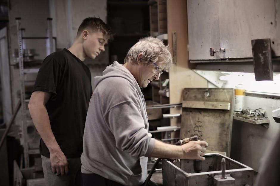
Using DC Motors for Assisted Dispensing
Integrating a DC motor into your manual vending machine offers a practical boost to dispensing heavier or awkwardly shaped items․ Rather than relying solely on manual force‚ a motor can provide the necessary torque to reliably release products․ Consider a setup where a hand crank activates the motor‚ creating a powered-assist system – maintaining the manual interaction while reducing user effort․

When selecting a motor‚ prioritize low voltage options (like 9V or 12V) for safety and ease of power supply․ Gear reduction is crucial; it trades speed for increased torque‚ essential for overcoming resistance․ The motor’s shaft can be coupled to the dispensing mechanism via a simple pulley system or a direct drive connection․ Remember to include a switch to control the motor’s operation and prevent continuous running․ Careful wiring and secure mounting are vital for a functional and safe automated assist․
Battery Power Considerations
For manual vending machines incorporating DC motors or simple automation‚ battery power offers portability and independence from mains electricity․ However‚ careful consideration must be given to battery type‚ voltage‚ and capacity to ensure reliable operation․ Alkaline batteries are a convenient starting point‚ but rechargeable options like NiMH or Li-ion provide long-term cost savings and reduced environmental impact․
Voltage must match the motor’s requirements – typically 9V or 12V․ Capacity‚ measured in mAh (milliampere-hours)‚ dictates runtime․ Higher mAh equates to longer operation between charges․ Consider the motor’s current draw and estimate usage frequency to determine appropriate capacity․ A battery holder or connector simplifies replacement and maintenance․ Always prioritize safety; use appropriate fuses and avoid short circuits․ Proper battery management extends lifespan and prevents potential hazards․
Specific Project Examples
Explore exciting builds! From gumball and pinball marvels to Oreo and milk dispensers‚ these projects demonstrate the versatility and fun of DIY vending machines․
DIY Gumball & Pinball Vending Machine
Combining classic fun with DIY ingenuity‚ this project creates a unique vending experience․ Imagine a machine that dispenses both gumballs and pinballs – a delightful fusion for any game room or hobby space! The core concept revolves around a manually operated system‚ often utilizing a rotating drum or a series of cleverly positioned levers․
Construction typically involves a cardboard or wooden frame‚ carefully designed to hold the gumballs and pinballs separately․ A coin mechanism‚ even a simplified manual one‚ can be incorporated for a more authentic vending feel․ The dispensing action is often achieved by rotating a wheel with appropriately sized holes‚ allowing one item to drop at a time․ This isn’t just a vending machine; it’s a captivating‚ interactive game!
Dejan Nedelkovski’s tutorial provides a fantastic starting point‚ showcasing how to bring this vision to life with readily available materials and a bit of maker spirit․ It’s a rewarding project that blends functionality with playful creativity․
Oreo & Milk Vending Machine Construction
Believe it or not‚ a fully functional Oreo and milk vending machine is achievable with minimal resources! This project demonstrates the power of ingenuity‚ utilizing primarily cardboard‚ a small DC motor‚ a nine-volt battery‚ and‚ of course‚ plenty of hot glue․ The construction focuses on creating separate compartments for the Oreos and a carton of milk․
The DC motor plays a crucial role in assisting the dispensing process‚ gently nudging the Oreos towards a delivery chute․ A simple lever system‚ activated manually‚ can trigger the motor and release a single cookie․ The milk dispensing requires a bit more finesse‚ potentially involving a tilting mechanism or a carefully positioned spout․
Ryan Bates’ creation exemplifies how accessible vending machine construction can be․ It’s a fantastic project for demonstrating basic mechanical principles and satisfying that sweet tooth with a custom-built marvel!
Customizable Snack Dispensing Machines
The beauty of DIY manual vending machines lies in their adaptability! Beyond Oreos and gumballs‚ these creations can be tailored to dispense a wide variety of snacks – from small candies and nuts to miniature toys and even homemade treats․ The core principles of lever-based or gravity-fed systems remain consistent‚ but the specific design will vary based on the snack’s size‚ shape‚ and fragility․
Consider building modular compartments within the machine to accommodate different snack types․ Adjustable chutes and dispensing mechanisms allow for precise control‚ preventing jams and ensuring a smooth delivery․ Experiment with different materials – wood offers durability‚ while cardboard provides affordability and ease of modification․
Dejan Nedelkovski’s work inspires makers to push boundaries‚ creating truly personalized vending experiences․ Let your imagination run wild and build a snack machine perfectly suited to your preferences!

Advanced Features & Modifications
Elevate your creation! Explore manual coin mechanisms‚ expanded product capacity‚ and aesthetic customizations to build a truly unique and functional vending machine․
Coin Mechanisms & Payment Systems (Manual)
Implementing a manual payment system adds a layer of realism to your DIY vending machine․ While fully automated solutions require electronics‚ a simple‚ mechanical approach is achievable and aligns with the “manual” ethos․ Consider utilizing a basic lever and gate system where inserting a coin of the correct size and weight triggers the dispensing mechanism․
This can be constructed from cardboard‚ wood‚ or even repurposed materials like plastic containers․ The key is precise calibration to accept only the intended denomination․ A tilting platform activated by the coin’s weight is another viable option․ More complex systems might involve a rotating drum with coin-sized slots‚ requiring the correct coin to align and release a lever․
Remember‚ the goal isn’t foolproof security‚ but a fun and engaging interaction․ Focus on creating a reliable system that consistently releases a product upon valid “payment‚” enhancing the overall vending experience․ Thorough testing is crucial for smooth operation․
Adding Product Variety & Capacity
Expanding your manual vending machine’s offerings requires thoughtful design adjustments․ To accommodate diverse products – from gumballs to cookies – modular dispensing units are ideal․ Each unit can be tailored to the specific size and shape of the item‚ ensuring reliable release․ Consider using adjustable dividers within the product columns to prevent jamming and maintain organization․
Increasing capacity often means scaling up the machine’s overall dimensions or cleverly utilizing vertical space․ Stackable dispensing trays‚ similar to those found in commercial machines‚ can significantly boost storage․ However‚ remember that a larger machine demands a more robust frame and dispensing mechanism to handle the increased weight and complexity․
Prioritize accessibility for refilling․ Removable panels or doors simplify restocking‚ making the machine more user-friendly․ Careful planning ensures both variety and ample supply are readily available․
Aesthetic Enhancements & Customization

Transform your functional creation into a visual centerpiece! Aesthetic enhancements breathe life into your manual vending machine․ Consider vibrant paint schemes‚ themed decals‚ or even incorporating reclaimed materials for a rustic look․ Clear acrylic panels allow a tempting view of the available products‚ boosting appeal․
Customization extends beyond visuals; Add personalized signage‚ branding elements‚ or interactive features like a hand-painted product menu․ Lighting‚ even simple LED strips‚ dramatically improves visibility and creates an inviting atmosphere․ Think about the overall style – retro‚ modern‚ whimsical – and tailor the design accordingly․
Don’t underestimate the power of detail․ Decorative trim‚ unique coin slots‚ or a custom-built dispensing lever can elevate the machine’s aesthetic․ Let your creativity flow and build a vending machine that reflects your personality!